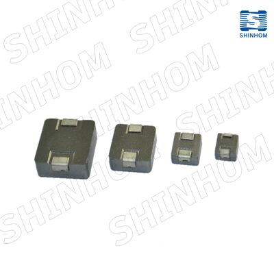
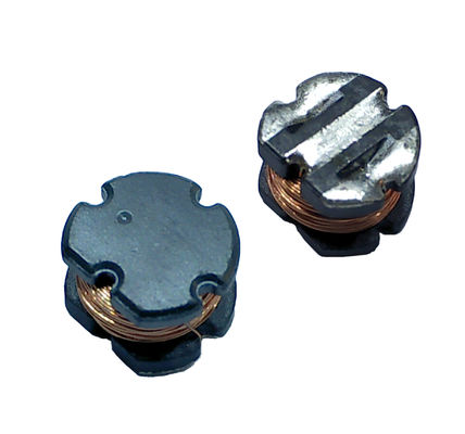
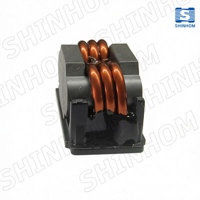
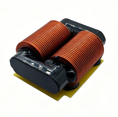
ACST-2 Series PCB Mount High Precision Current Transformers with Up to 15A Maximum Current Range Available
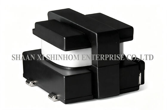
The ACST-2 series high-precision PCB-mount current transformer is designed for switching power supply current sensing applications. The rated current is up to 15A, with a frequency range of 10kHz to 200kHz. Four standard turns ratio options are available: 1:50, 1:100, 1:200, and 1:300, with corresponding secondary turns of 50, 100, 200, and 300 turns. The product uses a 1-turn primary winding and a 130°C insulation system. Isolation voltage is 3750Vrms, meeting IEC950 insulation requirements. It supports both unipolar and bipolar operating modes. It is widely used in switching power supply current sampling, overcurrent protection, and feedback control applications.
FEATURES
- Meets IEC950 insulation requirements
- 3750Vrms primary to secondary breakdown voltage
- Frequency range 10kHz to 200kHz
- Current range: up to 15A maximum
- Turns ratio: 1:50, 1:100, 1:200, 1:300 available
- Operating temperature: -40 to 85°C
Applications
-
Switching power supply current sensing
-
Overcurrent protection circuits
-
Current feedback control
-
High-frequency power converters
-
Unipolar switching power supplies
-
Bipolar switching power supplies
-
DC-DC converters
-
Pulse current monitoring
TECHNICAL INFORMATION
- These current sense transformers have a 1 turn primary winding, secondary turns (Ns) as indicated in the table,and a 130℃ insulation system.
- The reference values are for unipolar operation, 50kHz,40% duty factor, and an estimated 55℃ temperature rise.
- The maximum useable peak sense current (IPK) depends on temperature rise or core saturation, which should be evaluated for the operating conditions.
- These Current Sense Transformers are recommended for switch mode power supply applications, unipolar or bipolar,operating at frequencies from10kHz to 200kHz.
- The scale factor (KVI) is proportional to the terminating resistor(RT) and isequal to 1 volt/amp when RT=NS.
- The secondary inductance (Ls) is measured at 15kHz and 0.5V for ACST-2050,1V for ACST-2100, 2V for ACST-2200 and 3V for ACST-2300.
Notes: Product specifications can be customized
FAQ
Q: How is the scale factor calculated for the ACST-2 series?
A: The scale factor KVI is proportional to the termination resistor RT. The formula is KVI = 1V/A × (RT / Ns) , where Ns is the number of secondary turns. When RT = Ns (in Ω) , KVI = 1V/A, meaning 1A of primary current produces 1V of secondary output voltage. For example, for the ACST-2050 (Ns=50) , with a 50Ω termination resistor, 1A primary current produces 1V secondary output.
Q: How to choose the right turns ratio?
A: Turns ratio selection depends on the primary current range and the required secondary sampling voltage. A lower turns ratio (e.g., 1:50) has fewer secondary turns, higher output current, and is suitable for larger current sensing. A higher turns ratio (e.g., 1:300) has more secondary turns, lower output current, and is suitable for smaller currents or applications requiring higher output voltage. We recommend selecting based on the peak primary current and termination resistor value.
Q: What is the difference between unipolar and bipolar operating modes?
A: In unipolar mode, the primary current always flows in the same direction (positive or negative), commonly found in topologies such as flyback converters. In bipolar mode, the primary current alternates between positive and negative, commonly found in topologies such as push-pull and full-bridge converters. The ACST-2 series supports both modes. Reference performance data is provided at 50kHz with a 40% duty cycle.

 Your message must be between 20-3,000 characters!