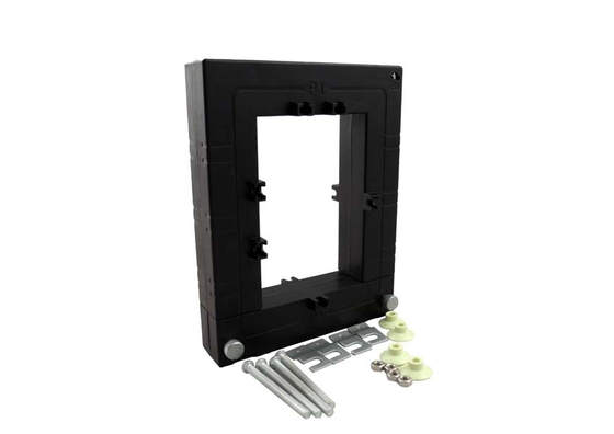
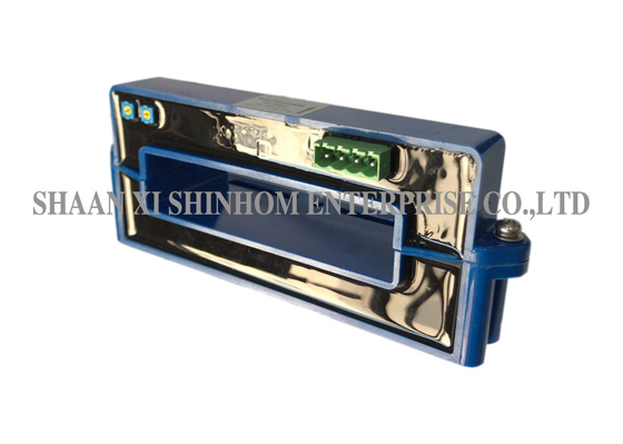
The HBC-LAP series closed-loop Hall effect current sensor uses a closed-loop (compensation) principle, providing electrical isolation between the primary and secondary circuits. It accurately measures DC, AC, or pulse currents with a measuring range of 0-200A. The product has a supply voltage of ±12V to ±15V (±5%) and a rated output current of 100mA±0.5% or 125mA±0.5%. It offers high accuracy and easy installation. Dynamic performance testing uses a single bar fully filling the primary hole, with the primary wire wound around the top of the sensor for optimal magnetic coupling. It is widely used in welding power supplies, battery-powered applications, AC variable speed drives, servo motor drives, switching power supplies, UPS, and DC motor drive static converters.
| HBC100LAP | HBC125LAP | HBC200LAP | ||
| Rated Current(IPN) | 100 | 125 | 200 | A |
| Measure Range(IP) | 0~±200 | 0~±200 | 0~±300 | A |
| Rated Output Current(ISN) | 100±0.5% | 125±0.5% | 100±0.5% | mA |
| Supply Voltage(±5%) | ±12~±15 | V | ||
| Supply current loss | 16(@±15V)+IS | mA | ||
| Test resistance | with±12V @±IPNmax | 14(min) 52(max) | 0(min) 26(max) | Ω |
| @±IPmax | 14(min) 17(max) | 0(min) 4(max) | Ω | |
| with±15V @±IPNmax | 40(min) 72(max) | 0(min) 56(max) | Ω | |
| @±IPmax @±300Amax | 40(min) 40(max) | 0(min) 8(max) | Ω | |
| Turns ratio | 1:1000 | 1:1000 | 1:2000 | |
| Sec resistance | 33 | 33 | 76 | Ω |
| Offset current | ≤±0.2 | mA | ||
| Offset current Drift | ≤±0.5 | mA | ||
| Response Time | <1 | µs | ||
| Linearity | ≤±0.2 | %FS | ||
| Insulation voltage | 50(60)HZ,1min,3 | KV | ||
| di/dt | >100 | A/μs | ||
| Bandwidth(-3dB) | DC…100 | KHz | ||
| Operating Temperature | -40~+85 | ℃ | ||
| Storage Temperature | -40~+105 | ℃ | ||
![]()
Notes: Product specifications can be customized
A: The two output currents correspond to different turns ratios and measuring range configurations. Both 100mA and 125mA are standard industrial output signals. Selection should be based on the input range and accuracy requirements of the downstream measurement equipment. Please consult our technical support team for specific recommendations.
A: Winding the primary wire around the top of the sensor achieves optimal magnetic coupling, ensuring measurement accuracy and dynamic performance. We recommend following the installation method specified in the product datasheet for optimal performance.
A: You can submit a sample application through our website or email. Please provide your company information and target model. Samples are free of charge and will be shipped within 3-5 working days. Mass order lead time is generally 2-8 weeks.